Basic concept
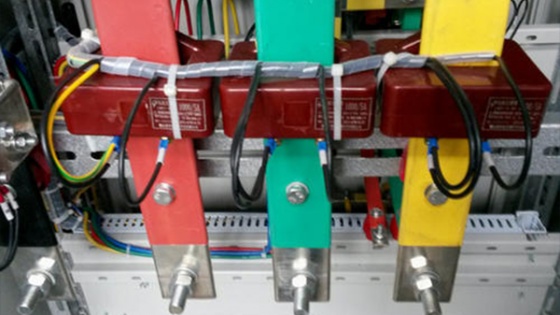
The principle of current transformer is based on the principle of electromagnetic induction. The current transformer consists of a closed core and winding. The number of turns in the primary winding is very small, and it is strung in the current line that needs to be measured, so it often has all the current flowing through the line, and the number of turns in the secondary winding is relatively large, and it is connected in the measuring instrument and the protection loop. When the current transformer is working, its secondary loop is always closed, so the impedance of the series coil of the measuring instrument and the protection loop is very small. The working state of the current transformer is close to short circuit.
Working principle
In the power generation, substation, transmission, distribution and electricity lines, the size of the current is very large, from a few amps to tens of thousands of amPs. In order to facilitate measurement, protection and control, it is necessary to convert to a more uniform current, and the voltage on the line is generally relatively high, such as direct measurement is very dangerous. The current transformer plays the role of current conversion and electrical isolation.
For the pointer type ammeter, the secondary current of the current transformer is mostly ampere-level (such as 5A, etc.). For digital meters, the sampled signal is generally milliamperes (0-5V, 4-20mA, etc.). The secondary current of the miniature current transformer is milliamperes, which mainly acts as a bridge between the large transformer and the sampling.
Miniature current transformers are also called "instrument current transformers". (" Instrument current transformer "has a meaning of multi-current ratio precision current transformer used in the laboratory, which is generally used to expand the instrument range.)
Current transformers and transformers are similar to work according to the principle of electromagnetic induction, transformers transform voltage and current transformers transform current. The winding (number of turns is N1) where the current is measured by the current transformer is called the primary winding (or the primary winding or primary winding); The winding connected to the measuring instrument (number of turns N2) is called the secondary winding (or secondary side winding, secondary winding).
The current ratio between the primary winding current I1 and the secondary winding I2 of the current transformer is called the actual current ratio K. The current ratio of the current transformer working at the rated current is called the rated current ratio of the current transformer and is represented by Kn.
Kn=I1n/I2n
The role of Current transformer (CT) is to convert the primary current with a larger value into a secondary current with a smaller value through a certain ratio, which is used for protection, measurement and other purposes. For example, a current transformer with a ratio of 400/5 can convert the actual 400A current into 5A current.